BENDIX BW1455 Manual de usuario

Busca en linea o descarga Manual de usuario para Herramientas Eléctricas BENDIX BW1455. BENDIX BW1455 User's Manual Manual de usuario

  • Descarga
  • Añadir a mis manuales
  • Imprimir
  • Pagina
    / 6
  • Tabla de contenidos
  • MARCADORES
  • Valorado. / 5. Basado en revisión del cliente
Vista de pagina 0
1
®
Bendix
®
AH-4
Air Hydraulic Intensifier
SD-11-1357
DESCRIPTION
The AH-4
is an air-over-hydraulic intensifier available with
pressure ratios of 13.5 to 1, 17 to 1 and 23.5 to 1. The air
chamber is a rotochamber, either type 30, 36 or 50. The
master cylinder design is identical in all units; however, the
master cylinder is available with seals for hydraulic brake
fluid, or for mineral oil. The master cylinder displaces 6 cubic
inches with the type 36 or type 50 actuator and 4.6 cubic
inches with the type 30.
The type 30 unit is designed for dusty operation, as in off-
highway, with the non-pressure cavity protected by a tight
fitting head and a filter for breathing non-pressure air.
The master cylinder may have a remote or direct mounted
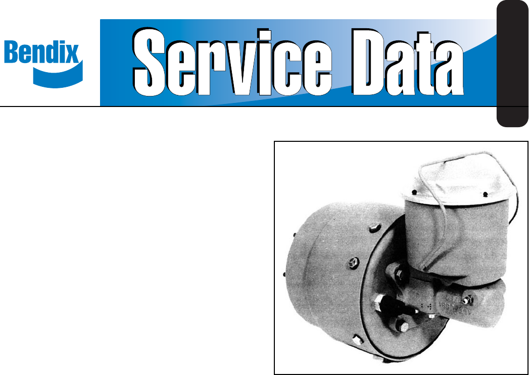
reservoir. Fig. 1 shows a 23.5 to 1 unit with integral reservoir.
OPERATION
The AH-4
intensifier is normally used to provide hydraulic
pressure to hydraulic disc brakes on an air braked vehicle.
It may be used in any application where it is desired to
“intensify” available air pressure to a higher hydraulic
pressure. 100 psi air pressure introduced to the center port
at the rear of the rotochamber will produce approximately
1,350 psi hydraulic pressure at the master cylinder delivery
port with a type 30 rotochamber, 1,700 psi with a type 36
rotochamber, and approximately 2,350 psi with a type 50
rotochamber.
PREVENTIVE MAINTENANCE
Important: Review the warranty policy before performing
any intrusive maintenance procedures. An extended warranty
may be voided if intrusive maintenance is performed during
this period.
Because no two vehicles operate under identical conditions,
maintenance intervals will vary. Experience is a valuable guide
in determining the best maintenance interval for a vehicle.
Every Month, After 8,000 Miles, or 300 Operating Hours
1. Remove the cover and gasket from the brake fluid
reservoir, taking extreme care to first remove all dirt and
foreign material so that no foreign material is permitted
to get into the hydraulic fluid. If the fluid lever is low,
proper fluid should be added. CAUTION - The cover and
gasket will each indicate whether hydraulic brake fluid
or mineral oil should be added. The gasket for brake
fluid is black and the gasket for mineral oil is green.
2. Check the stroke warning switch by grasping the switch
extension rod underneath the rubber boot and pulling
firmly. With the ignition turned on, the warning light in
the cab should light. NOTE: If the warning light comes
on during a service application, the vehicle should be
brought in for service immediately.
3. Check tightness of mounting nuts, air and hydraulic
fittings.
Every 12 Months, 100,000 Miles, or 3,600 Operating Hours
1. Disassemble and clean all parts.
2. Install new rotochamber diaphragm, reservoir gasket,
seals or any parts worn or damaged.
OPERATING AND LEAKAGE TESTS
Operating Test
1. With the air system built up to governor cut-out pressure,
make and hold a full brake application. Hold for at least
5 minutes. Check the rear of the rotochamber and the
rotochamber head vents for air leakage by coating with
a soap solution.
2. While still holding the brake application, check for
hydraulic fluid leaks at all fitting connections and at the
disc brake calipers.
Vista de pagina 0
1 2 3 4 5 6

Indice de contenidos

Pagina 1 - Air Hydraulic Intensifier

1®Bendix® AH-4™ Air Hydraulic IntensifierSD-11-1357DESCRIPTIONThe AH-4™ is an air-over-hydraulic intensifier available withpressure ratios of 13.5 to

Pagina 2 - INSTALLING ON VEHICLE

2OUTER DIAPHRAGMCLAMPFIGURE 1DIAPHRAGMGUIDESTROKE WARNING SWITCHFILTER176842353. Observe the stroke warning light. If the master cylinderpiston seal l

Pagina 3 - DISASSEMBLY

3FIGURE 23.19 MAX.60.743.12 REFSTROKE891110DISASSEMBLYRotochamber from Master Cylinder FIGURE 11. Remove four cap screws (1), and remove the mastercyl

Pagina 4 - ASSEMBLY

4FIGURE 3FIGURE 4FIGURE 5ASSEMBLYRotochamber1. Position the diaphragm on end in the inner diaphragmclamp (Fig. 1). The smaller diameter end of thediap

Pagina 5 - FIGURE 9

5FIGURE 7FIGURE 6FIGURE 8FIGURE 93. Install the new o-ring (2) on the cap nut after lubricatingwith the fluid to be used in the master cylinder or Dow

Pagina 6 - OR DEATH:

6WARNING! PLEASE READ AND FOLLOW THESEINSTRUCTIONS TO AVOID PERSONAL INJURYOR DEATH:When working on or around a vehicle, the followinggeneral precauti

Comentarios a estos manuales

Sin comentarios